Category Archives: Electronics

RepRap is Alive!

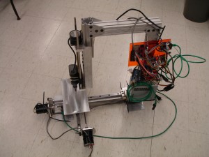
I’ve been wrenching for a few weeks to machine enough pieces to create a CNC plastic extruder (RepRap / Makerbot). I’ve got the CNC part done, now I have to get the extruder and heated bed up and running so I can start RPing parts.

Sector67 Forum Thread

I’ve gotten a few questions as to what you’re looking at, if you’re completely unfamiliar a visit to Wikipedia should clear things up.

It’s made out of 2″ x 2″ extruded aluminum channel, the railed looking stuff that makes up the top of the arm and the drop for the spindle (dremel) is called 80/20, it’s fairly expensive but is very precise and saves a lot of time for some projects.

The Z axis is the classic over constrained parallel rods, I pulled the rods out of a pair of identical printers and then drilled and reamed to size the end blocks and the slider block, which is just a chunk of delrin plastic. The bad part about using a plastic block for a sliding surface is that you have a drill/ream it over significantly to get it the right size, which in my case just means it’s sloppy and will be replaced by linear bearing when it becomes the weakest link in the machine for precision or stiffness.

The bottom end X-Y axes are THK precision linear bearing. I picked this out of discarded equipment at the university, which I understand it not available to “normal people”. I found out a few years after I picked it up that it’s $0.43/millimeter (yep, that’s a half of a dollar per the thickness of your fingernail, it’s expensive). The bearing carriages are ~$130/each. I was fortunate enough to find a pair of 18″ linear track and a pair of bearings still in their well oiled bags! They do have lash in them and should certainly be run in parallel or with a precision guide track for stiffness/rigidity but for my application (milling light plastics and depositing plastic in an additive process) it’s not a major concern this early in the project.

The other common question is how much does this thing cost. So far I have $199 for the full generation 3 Makerbot electronics (thanks Zach et al., they work great!) and $4.11 for 3 x 1″ long 1/4-20 nuts that are used on each of the axes (True Value). The rest has been collected or given to me by others.
These are a few of my favorite stores. . .

I’ve been meaning to post this for a while now 🙂

Electronics vendors:
Digikey (Excellent search function, expensive but very good pictures, lots of products too)
Mouser (lots of what digikey has but no pictures! Great for Delphi / Amphenol connectors)
Newark (bigger weirder stuff, careful some stuff ships from Farnell in the UK)
Jameco (Search is terrible, but if you can’t find it anywhere else. . .)
Allied Electronics (Cheap amphenol. . .)
Waytek (cheap for bulk connectors and wire, next day shipping)

Arduino:
Adafruit (cheap and usually has what I need, I’d rather pay a little more to support a still growing startup)
Sparkfun (expensive but a good one-stop-shop)

Electronics Surplus:
All Electronics

China Direct Electronics:
Futurlec (Cheap, good customer support, responsive, shipping takes a while – as indicated up front)
Deal Extreme (holy cheap, lots of people on eBay/discount stores are buying and drop shipping from them)
Sure Electronics (Lots of great cheap parts, you have to add them to your cart and check shipping after each item though, they’re making up some of their costs by charging shipping for each item – I received everything 3rd day after I ordered it though, which is amazing)
MPJA Ships from Florida, cheapest breadboard prices I’ve ever seen, not sure about anything else.

Materials:
McMaster-Carr (Expensive, ships quick, stocks a lot, great pictures/details on products, search rocks)
Grainger (Search sucks, plumbing stuff/etc much cheaper than McMaster, if you can find anything. . .)
MSC Direct (Tooling, industrial consumables)

Tools
Harbor Freight (If you’re on a budget you can’t get better than HF tools, but make sure you read the reviews)

How to Program Sparkfun Arduino Pro Mini

I just picked up a Sparkfun Arduino Pro Mini board for a project.  It’s a really nice really compact board with almost all of the pins broken out on it.  If you already own a Duemilanove you can easily program it using the Arduino software, just pull the Atmega chip off the Duemilanove and then using the shortest side of the board’s contacts, wire:

reset – grn
tx
rx
vcc
gnd
blank – blk

The words grn and blk are silkscreened on the board to denote which pins are which.  You could of course use a RS232->TLL converter to program this as well, but using the Duemilanove is really convenient as it pulls the reset pin low for you.

On the topic of this Pro Mini board, I had a few e-mails back and forth with Sparkfun trying to figure out what the actual maximum input voltage for the board is, Sparkfun’s Website lists it at 12VDC max, the EagleCAD schematics list it as 16VDC, and the datasheet for the voltage regulator list it as operational maximum 16VDC, with an absolute maximum of +/-20VDC before damage occurs.

Also noted is that the oscillator on this board is absolute crap, I have a timing critical application that I intended to use this board on, using a stopwatch and a Duemilanove and this board, both running identical software and hardware configurations:

15hours 37 minutes elapses, the Duemilanove is exactly in sync with the stopwatch still, the Pro Mini has gained 1 minute and 1 second. I ran this test several more times with identical results, the stop watch and the Duemilanove are in sync, with the Pro Mini gaining time each time, always about 20 second per 5 hours elapsed time, which is not acceptable in my application.

I swapped the Sparkfun crystal/resonator for one of my own resonators and ended up with the same crappy timing. I finally switched out the resonator for a crystal and a pair of capacitors tied to ground and was able to clean up the timing mostly, it’s still gaining a second for every 40 minutes it runs for, it was previously 15 so it’s improved, but not ideal. I’m going to ditch using the Sparkfun board for my own layout on the next iteration.

MAX6675 Thermocouple Amplifier EagleCAD

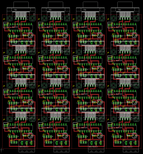
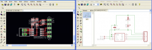
I created a little SMT board for the MAX6675 thermocouple amplifier in EagleCAD if anyone out there is in need of a board.  It’s very simple layout but it is a bit noisy, definitely expect to average samples coming from this chip (/board?).  Other improvements would be adding a thermistor as the CJC (cold junction compensation) on the board so you can accurately offset the junctions at the board where you break the thermocouple wire and transition over to copper (which creates another TC junction unintentionally so you must compensate for it).

MAX6675 TC Amplifier Board and Schematic

MAX6675 TC Board Schematic and Board (and Panelized)

HP 3325B Function Generator

I saved a HP3325B from the trash almost 6 months ago which is an awesome score.  When I had first powered it up it threw a FAIL 023 error, I put it under my desk and decided to get it out and patch it up today.

First key bit of information is that HP / Agilent are absolutely spectacular companies for providing service manuals, product manuals, and datasheets well beyond the retail life of their instruments.  You can still pick up documentation directly from Agilent here.

In digging through the datasheet you can see that a FAIL 023 means we’re having a problem with the dc offset, so I printed off the relevant service information (groups K,J) and prepared for the worst.  After powering the machine on at my desk I was again met with the FAIL 023 when requesting a sine wave, and a new error was a FAIL021 when requesting a square wave.  I then out of chance cycled through the other 3 settings (triangle, etc) and returned to the square wave and sine waves to discover that the errors had went away!  It’s likely that I had a stuck/hung up relay and switching away from square and sine waves cycled something into place again.  We’ll see how long it lasts but hopefully I’ve just picked up a nice piece of equipment.

Additionally while I was reassembling the covers, turning the instrument from side to side resulted in a nice pinball sound, I swung it back in forth until I was greeted with 3 washers on my desk, I can’t imagine that these were helping with things but they’re out now.  Looks like they came off the main power transformer which someone had helpfully duct-taped into place at some point.

Windows 7 Hyperterminal Replacement

Well, firstly  a moment of silence for our lost old friend hyperterminal.  But you just want to get serial data flying around again right?  I spent about 30 minutes downloading and finding no free serial port solutions for Windows 7 until I remembered PuTTY!

You can download PuTTY here, and either install it or run the exe.  PuTTY will launch, select

Connection type: Serial

Set your configuration and hit open and you should be in good shape.  You can set up local echo and all of your other preferences through the myriad of menus at the left.  Most importantly you’ll again have a lightweight serial console for Windows 7.

I2C Communication Arduino MEGA to Duemilanove

If you’re wondering how to get I2C running from your MEGA to Duemilanove Arduino boards here’s the scoop:

MEGA Pin 20 is SDA (Serial Data)

Duemilanove Analog Pin 4 is SDA

MEGA Pin 21 is SCL (Serial Clock)

Duemilanove Analog Pin 5 is SCL

Hook up SCL to SCL and SDA to SDA across the boards, also hook up ground between the two boards.  You do NOT need to connect the +5V between boards.

You’ll need  SCL and SDA to be pulled up (to +5V with resistors, between 2.2kOhm and 47kOhm), it will run without them but its recommended to make your bus within specification.

Example bus from Instructables.
MEGA Pinout information (search for i2c on the page).

EagleCAD Panelize / Copy and Paste in Board View

Took too long to figure this out.  EagleCAD of course likes to keep the schematic and the board synchronized, and it won’t back annotate edits on the board into the schematic.  These are all happy, logical things that keep board designers sane.  However!  When it comes time to panelize or make multiple copies of a board layout for printing it won’t allow you to copy and paste sections of the board because it doesn’t want to perform the backannotation.

It took me a while of searching, but Keith’s Electronics Blog makes it sound like a cake-walk, it’s not that easy.  However, a random forum post gets it right:

Open your first file
Execute panelize.ulp
[It's in the top bar, icon with ulp in black text on a white "sheet of paper"]
Group
Cut (don't forget origin click)
Open your other file
Save as different file name
Execute panelize.ulp
Paste the other board in [the part you're trying to panel that you previously "cut"]

EagleCAD RS232 Driver Panelized

EagleCAD RS232 Driver Panelized

EagleCAD Layout – Arduino Base

If you’re looking for an Arduino basic layout in EagleCAD (all clock/power/ICSP lines run but nothing else) here it is:

Arduino Base Layout

The board layout is troublesome on a single layer board, most of the I/O are currently blocked with power or ground, I’ll leave that up to you to figure out what you want to do.

If you’re looking at this, you’ll probably be really interested in this single sided Arduino layout.

Passive Infrared Controlled Outlet

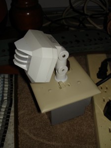
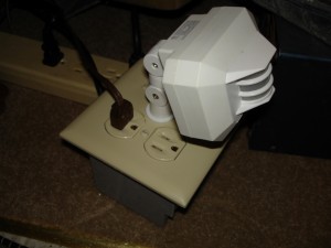
I created this PIR (Passive Infrared) outlet for the lamp by my door so I no longer have to flip the switch when I walk in with my hands full.  I know you can buy wall switches with PIR in them but I haven’t seen an outlet yet.

PIR Switched Outlet

PIR Switched Outlet

PIR Switched Outlet

PIR Switched Outlet

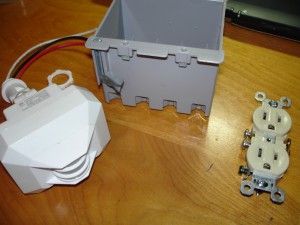
I basically took a dual-gang electrical junction box, an outlet and a standard switch, I drilled a hole in the center of the cover plate and mounted the PIR sensor (Walmart special, $9, intended for a Brinks outdoor light).  The PIR sensor takes hot and neutral and switches out hot when it’s triggered by a change in thermal trace.  This switched hot was then wired into the outlet and whatever is plugged into it is obviously now switched.  So, what’s the switch for you ask?  It’s simply to override the PIR sensor and keep the light on when I’m sitting on the couch.  It’s just wired in parallel into the outlet.

PIR Outlet Parts

PIR Outlet Parts