How to Program Sparkfun Arduino Pro Mini

I just picked up a Sparkfun Arduino Pro Mini board for a project.  It’s a really nice really compact board with almost all of the pins broken out on it.  If you already own a Duemilanove you can easily program it using the Arduino software, just pull the Atmega chip off the Duemilanove and then using the shortest side of the board’s contacts, wire:

reset – grn
tx
rx
vcc
gnd
blank – blk

The words grn and blk are silkscreened on the board to denote which pins are which.  You could of course use a RS232->TLL converter to program this as well, but using the Duemilanove is really convenient as it pulls the reset pin low for you.

On the topic of this Pro Mini board, I had a few e-mails back and forth with Sparkfun trying to figure out what the actual maximum input voltage for the board is, Sparkfun’s Website lists it at 12VDC max, the EagleCAD schematics list it as 16VDC, and the datasheet for the voltage regulator list it as operational maximum 16VDC, with an absolute maximum of +/-20VDC before damage occurs.

Also noted is that the oscillator on this board is absolute crap, I have a timing critical application that I intended to use this board on, using a stopwatch and a Duemilanove and this board, both running identical software and hardware configurations:

15hours 37 minutes elapses, the Duemilanove is exactly in sync with the stopwatch still, the Pro Mini has gained 1 minute and 1 second. I ran this test several more times with identical results, the stop watch and the Duemilanove are in sync, with the Pro Mini gaining time each time, always about 20 second per 5 hours elapsed time, which is not acceptable in my application.

I swapped the Sparkfun crystal/resonator for one of my own resonators and ended up with the same crappy timing. I finally switched out the resonator for a crystal and a pair of capacitors tied to ground and was able to clean up the timing mostly, it’s still gaining a second for every 40 minutes it runs for, it was previously 15 so it’s improved, but not ideal. I’m going to ditch using the Sparkfun board for my own layout on the next iteration.
National Instruments DIAdem Text @@ Commands

If you’ve ever used NI’s DIAdem for data analysis you know how useful it is for looking at and analyzing large datasets.  What you may or may not have discovered is the @@——@@ commands that can be used to display channel related texts anywhere in the program.

DIAdem helpfully gives you a list of available commands, but doesn’t tell you what they display or how to use them.
Program Command: @@ChnPropGet(No,Property name)@@
Formatting: @@ChnPropGet(1,”Description”)@@
Output: The 1st channel’s Description, other input could be Name, Unit, etc
Notes: Make sure to use quotes around the Property name and remember that the channels are counted from the very first channel onwards and found as “Number” in the channel information.

Command: @@CD()@@
Formatting: @@CD(1)@@
Output: The 1st channel’s Units

Command: @@ChD(Line,No)@@
Formatting: @@ChD(2,1)@@
Output: The 1st channel’s second data point value

Command: @@CL(No)@@
Formatting: @@CL(1)@@
Output: The 1st channel’s number of points (length)

Command: @@CNoXGet(Channel group number,No)@@
Formatting: @@CNoXGet(2,1)@@
Output: Finds the 2nd group’s first channel and returns it’s channel number (counting from the first channel.
Notes: Could be considered translating from relative position of a channel (in a group) to absolute position in the list of channels.

Couple of general notes, you can’t nest lookups (at least not in the text boxes, so it would be invalid to:

@@ChnPropGet(794,"Description")@@

and turn it into a lookup:
@@ChnPropGet(@@CNoXGet(15,1)@@,"Description")@@

Otherwise it’s pretty helpful to use these when labeling graphs/etc so you don’t have to constantly correct things.  DIAdem also builds in lots of string functions like trim/etc, so you can clean things up if necessary!

<Wordpress>  – I had all these formatted nicely in a table but WordPress ate itself trying to render it, hence the oddball list, sorry. </Wordpress>

MAX6675 Thermocouple Amplifier EagleCAD

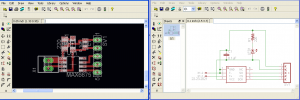
I created a little SMT board for the MAX6675 thermocouple amplifier in EagleCAD if anyone out there is in need of a board.  It’s very simple layout but it is a bit noisy, definitely expect to average samples coming from this chip (/board?).  Other improvements would be adding a thermistor as the CJC (cold junction compensation) on the board so you can accurately offset the junctions at the board where you break the thermocouple wire and transition over to copper (which creates another TC junction unintentionally so you must compensate for it).

MAX6675 TC Amplifier Board and Schematic

MAX6675 TC Board Schematic and Board (and Panelized)

Argonne National Lab

I took a field trip with work down to Argonne National Lab to see their engine labs. We also stopped by their photon source (used to generate x-rays).

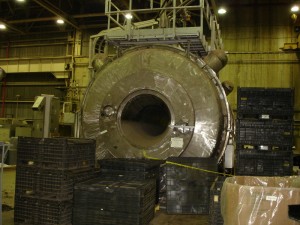
While we were walking through a storage area they pointed out a real version of the Hunt for Red October’s caterpillar drive, in reality called a “Magentohydrodynamic drive” which uses massive magnetic fields to induce flow in water.

Magnetohydrodynamic Drive

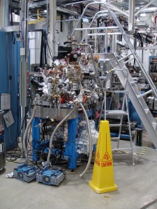
Pictures of the advanced beamline that they put materials/experiments in the way of to blast them with x-rays:

Advanced Photon Source

Advanced Photon Source

Advanced Photon Source

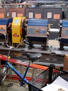
Here’s a picture of the accelerator used to get the photons up to warp speed. (99+% c )

Advanced Photon Source Accelerator

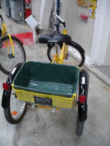
And I managed to find evidence of the infamous government’s Sector 7 as noted on this bicycle:

Proof of Sector 7

Finally, for being one of the most advanced research facilities in the world, they sure managed to keep things looking fresh out of WWII on the exterior, here we can see some of the outdoor exposed infrastructure leaking like a sieve, good thing it’s just steam:

Argonne National Lab Aging Infrastructure

HP 3325B Function Generator

I saved a HP3325B from the trash almost 6 months ago which is an awesome score.  When I had first powered it up it threw a FAIL 023 error, I put it under my desk and decided to get it out and patch it up today.

First key bit of information is that HP / Agilent are absolutely spectacular companies for providing service manuals, product manuals, and datasheets well beyond the retail life of their instruments.  You can still pick up documentation directly from Agilent here.

In digging through the datasheet you can see that a FAIL 023 means we’re having a problem with the dc offset, so I printed off the relevant service information (groups K,J) and prepared for the worst.  After powering the machine on at my desk I was again met with the FAIL 023 when requesting a sine wave, and a new error was a FAIL021 when requesting a square wave.  I then out of chance cycled through the other 3 settings (triangle, etc) and returned to the square wave and sine waves to discover that the errors had went away!  It’s likely that I had a stuck/hung up relay and switching away from square and sine waves cycled something into place again.  We’ll see how long it lasts but hopefully I’ve just picked up a nice piece of equipment.

Additionally while I was reassembling the covers, turning the instrument from side to side resulted in a nice pinball sound, I swung it back in forth until I was greeted with 3 washers on my desk, I can’t imagine that these were helping with things but they’re out now.  Looks like they came off the main power transformer which someone had helpfully duct-taped into place at some point.

How to Repair a Camshaft Position Sensor 1997 Ford Taurus

If you’re looking to swap out the camshaft position sensor (distributor, synchronizer) on a late 90’s Ford Taurus jump on over to the projects page where you can catch my photos and instructions on how to do it quickly.

Make Plastic Lego Train Tracks Work with 9V or 12V Trains

I’ve posted another project for those of you stuck with 9V or 12V Lego trains force to pay very steep prices on eBay for additional track (especially the straight track!). Head on over to the projects page to check it out. Ultimately it’s a pretty simple solution, you just need the aluminum flashing tape used commercially during building construction and cut into strips or stain-glass-makers copper or aluminum foil tape, stick it down on the tracks, smooth it out and it works out perfect.

Windows 7 Hyperterminal Replacement

Well, firstly  a moment of silence for our lost old friend hyperterminal.  But you just want to get serial data flying around again right?  I spent about 30 minutes downloading and finding no free serial port solutions for Windows 7 until I remembered PuTTY!

You can download PuTTY here, and either install it or run the exe.  PuTTY will launch, select

Connection type: Serial

Set your configuration and hit open and you should be in good shape.  You can set up local echo and all of your other preferences through the myriad of menus at the left.  Most importantly you’ll again have a lightweight serial console for Windows 7.

I2C Communication Arduino MEGA to Duemilanove

If you’re wondering how to get I2C running from your MEGA to Duemilanove Arduino boards here’s the scoop:

MEGA Pin 20 is SDA (Serial Data)

Duemilanove Analog Pin 4 is SDA

MEGA Pin 21 is SCL (Serial Clock)

Duemilanove Analog Pin 5 is SCL

Hook up SCL to SCL and SDA to SDA across the boards, also hook up ground between the two boards.  You do NOT need to connect the +5V between boards.

You’ll need  SCL and SDA to be pulled up (to +5V with resistors, between 2.2kOhm and 47kOhm), it will run without them but its recommended to make your bus within specification.

Example bus from Instructables.
MEGA Pinout information (search for i2c on the page).

AVL Smokemeter or Opacimeter Controller Software

If anyone is looking for a free terminal style controller for an AVL 415S Smokemeter or a AVL 439 Opacimeter I’ve posted the ones I use at work here.

You’ll want the very old school Terminal from Microsoft:

Microsoft TERMINAL

And the preset terminal buttons for the AVL 415S Smokemeter:

SMK_MCE

OR the LabVIEW interface for the AVL 415S Smokemeter:

LV Smokemeter Control
(Taken from this post)

And the preset terminal buttons for the AVL 439 Opacimeter:

OPACIMETER_TRM

OR the LabVIEW interface for the AVL 439 Opacimeter:

Opacimeter_Control
(Lightly modified from this one)