| |||||
 |


Replace LCD Backlight Inverter on Any Monitor for <$10 - Previously On Instructables
*-* Click images for Huge PicturesForeword
LCD monitors are getting on 10 years old now, so they're starting to be thrown away when the backlight inverter dies! Replacement inverters cost between $10-130
online (Ebay) depending on the monitor and then you'll have to put it in yourself, if you pay to have it repaired you'll be paying more then the cost of a new monitor.
I'll show you how to replace the bad inverter on any LCD by using inverters from CCFL effects lighting for really cheap!
I'll show you how to replace the bad inverter on any LCD by using inverters from CCFL effects lighting for really cheap!
Step One: Determine that the LCD Monitor has a Bad Backlight!
The first step is the make sure that your backlight is bad.
The main symptom is that the monitor powers on, the indicator LED acts correctly (green to start with and goes amber after entering into standby state). If you shine a flashlight either directly at the screen or at an extreme angle you can still make out the image but it is not being illuminated by the screen itself so it appears to be a black screen at first glance.
Take a look at the picture below, if you click the little i in the corner and view the full sized image you should be able to see a faint *hello world* in the background even though a picture without the flash would appear totally black. This is similar to what you should see with the flashlight

Image Notes
1. If you look carefully you can see "Hello World Hello World", so the monitor is working, just no backlight!
1. If you look carefully you can see "Hello World Hello World", so the monitor is working, just no backlight!
Step Two: Disassemble and Determine Number of Bulbs
The next step is to disassemble the monitor and check that nothing is obviously wrong with the inverter (unplugged, obvious electrical problem, etc) and that the light
bulbs are not smashed (no rattling glass or anything else).
Once you get into the monitor, there should be an inverter with a number of leads running out of it. All the CCFL bulbs that I've ever seen always have white and light blue or pink wires. There are typically between 2-6 bulbs in a monitor. Be careful with the inverter, there is typically several thousand volts that drive the CCFL bulbs, so this isn't your typical 12VDC circuit that you can ignore the possibility of electrocution!
Order the correct number of inverters to drive your bulbs, I ordered mine from Ebay for $2.95/inverter to which will drive a set of bulbs. You can do a search for CCFL lights here.
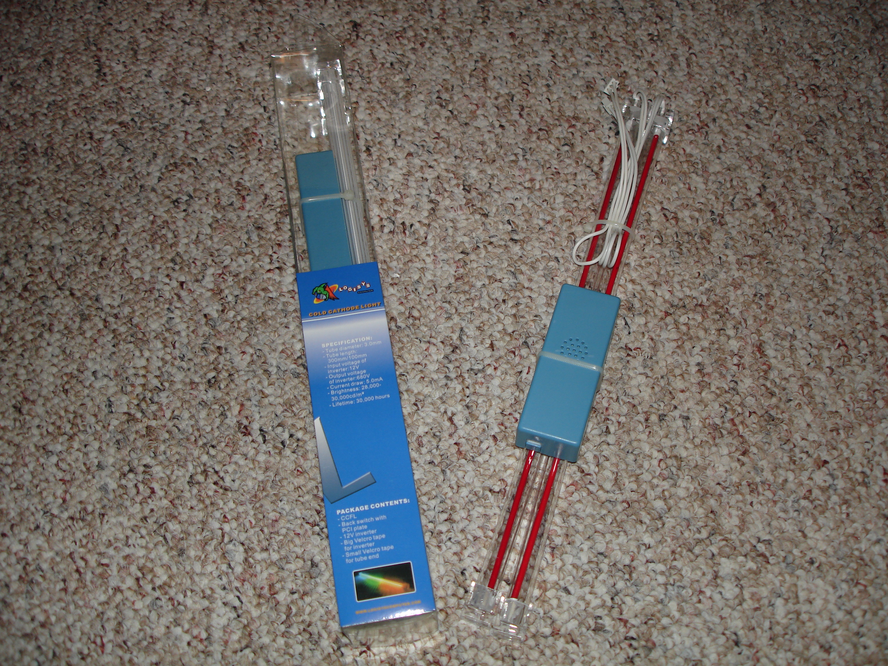
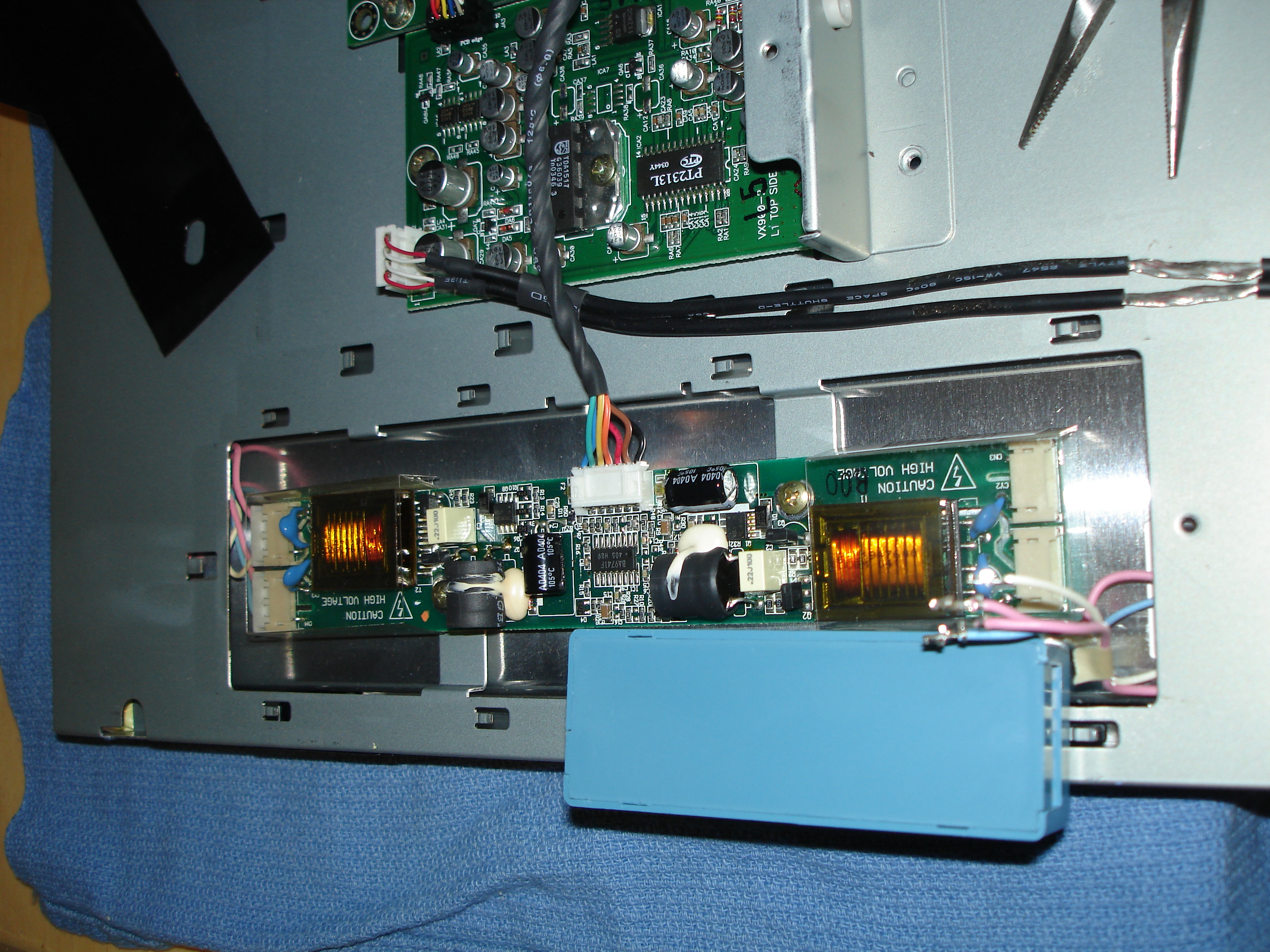
Image Notes
1. CCFL Lights for computer case effects, the inverters are really cheap and work well for the CCFL lightbulbs in the monitors
2. You can see the placement of the original inverters, where as the blue new replacement is just below the stock one.
1. CCFL Lights for computer case effects, the inverters are really cheap and work well for the CCFL lightbulbs in the monitors
2. You can see the placement of the original inverters, where as the blue new replacement is just below the stock one.
Step Three: Find Power
Now that you have replacement inverters you'll need to find someplace to power them. Since my new inverters take 12VDC at approximately 600 milliamps I'll need a
fairly good supply to tap from to power them both. I looked at the original inverter power wires but when momentarily pulled to ground they were only able to provide 300 milliamps each, so I won't be able to use the stock wiring.
I then looked closer to the power supply side of the monitor boards and found a labeled power wire running +12VDC to the main monitor board. I momentarily pulled that to ground and found about 3.5 amps so way more than enough to power the new inverters.
NOTE OF CAUTION! If you pull power from the power supply in the monitor you should realize that the back lights will then be on permanently as long as the monitor has power running to it! This was a problem for me, so I installed a switch to manually control the backlight power. If you want to you could use the original inverter power wires to run a relay to turn the new backlights on and off when the monitor goes into standby. The choice is yours!
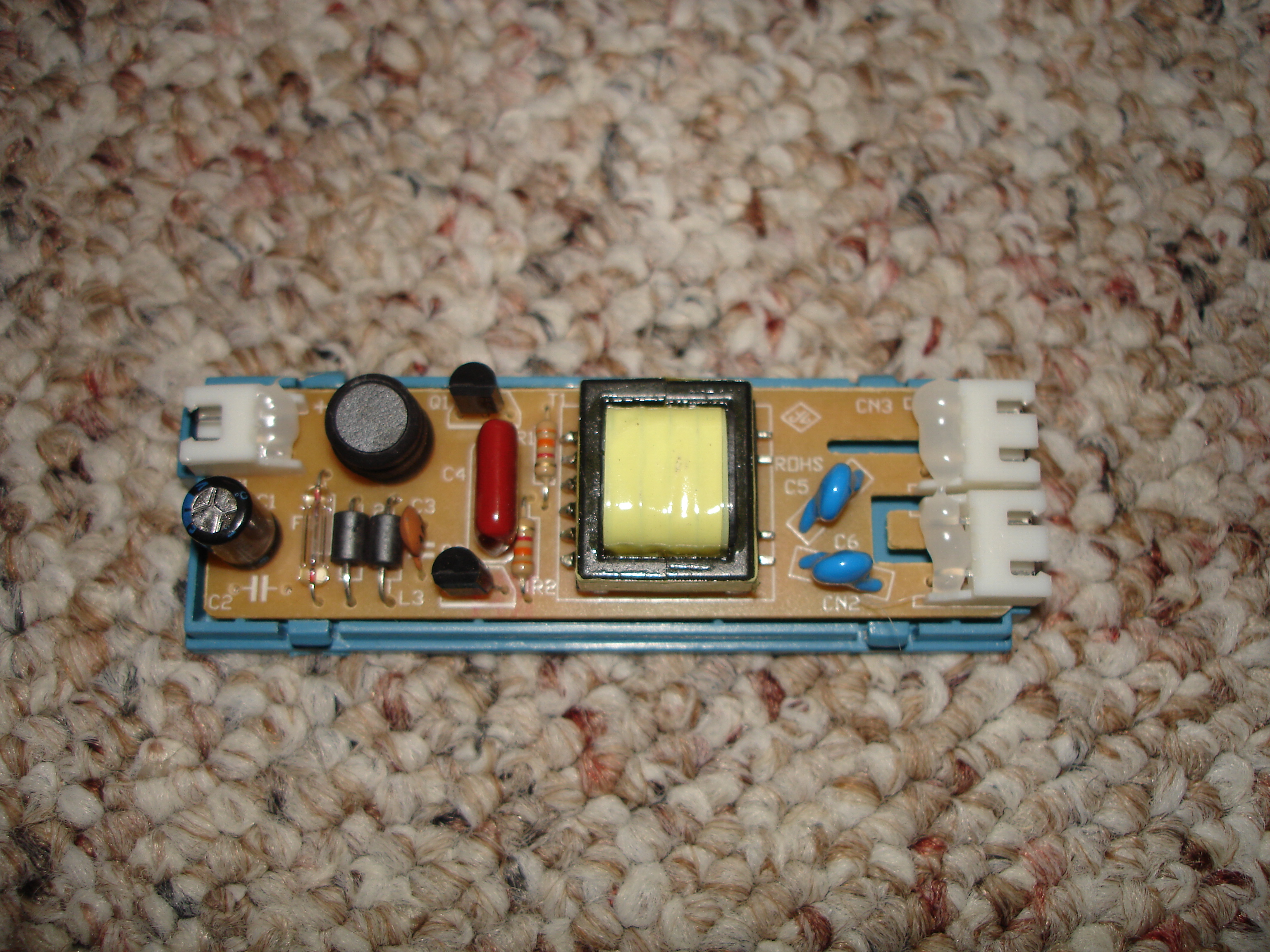


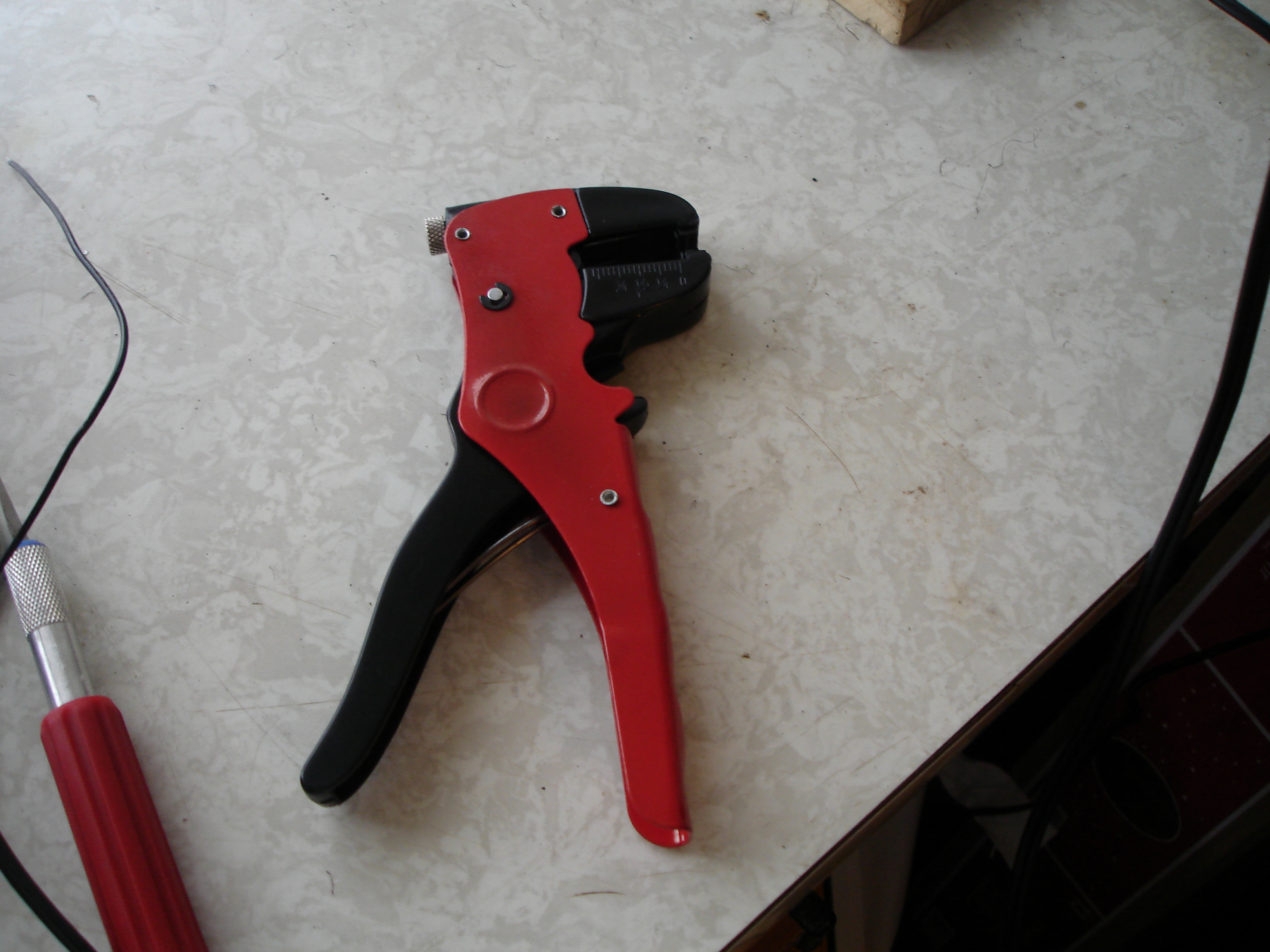
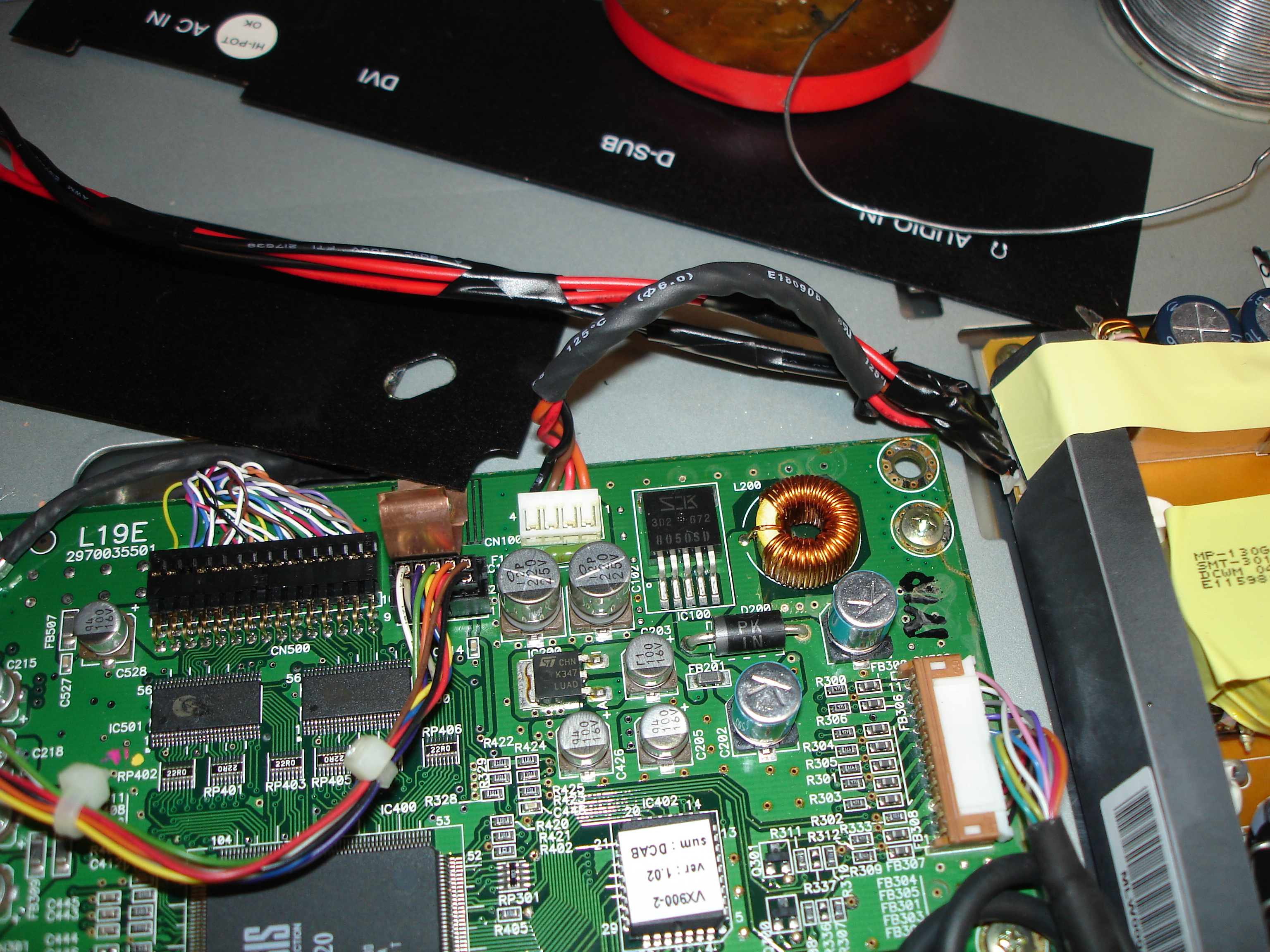
Image Notes
1. Left section is power filtering and fuse, then yellow transformer that steps up voltage, and the the blue capacitors are filters output to the high voltage connectors at the far right in white.
2. Should be able to fit 2 replacement inverters here.
3. Stripping power directly from the power supply.
4. Wires included in the inverter kit are plently long.
5. The best $.99 wire strippers money can buy, I have every type of wirestrippersyou can get and these win over everything! here at Harbor Freight - I bought them on sale, they are periodically.
6. Added power wires and carefully taped everything over.
Step Four: Add Inverters
Now that you've got power, you'll want to remove and unplug the old inverter and then mount up the new inverters. I chose to use the original cases for the inverters and just run a screw through the bottom in the area underneath the transformer where there are no other traces.
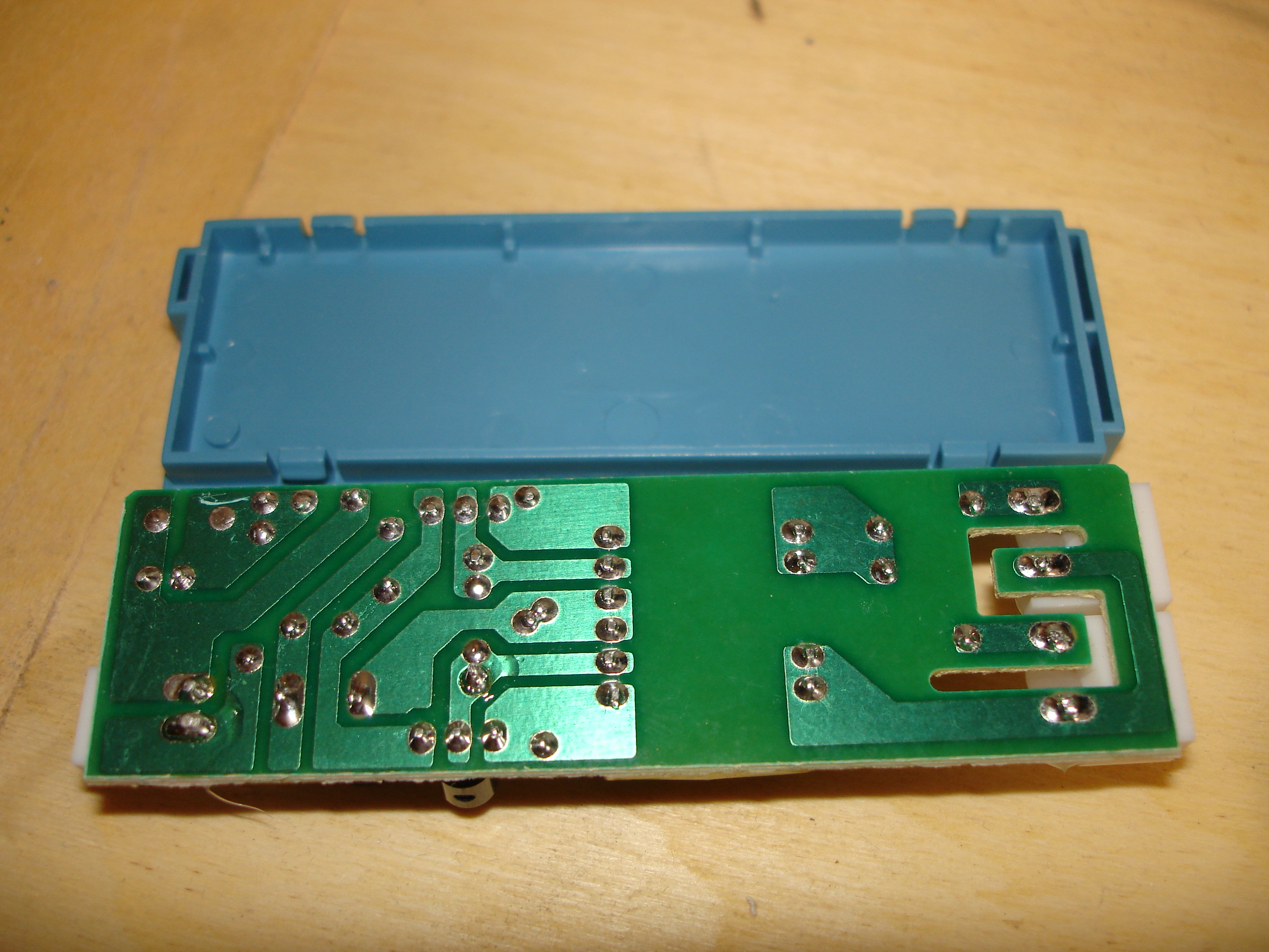
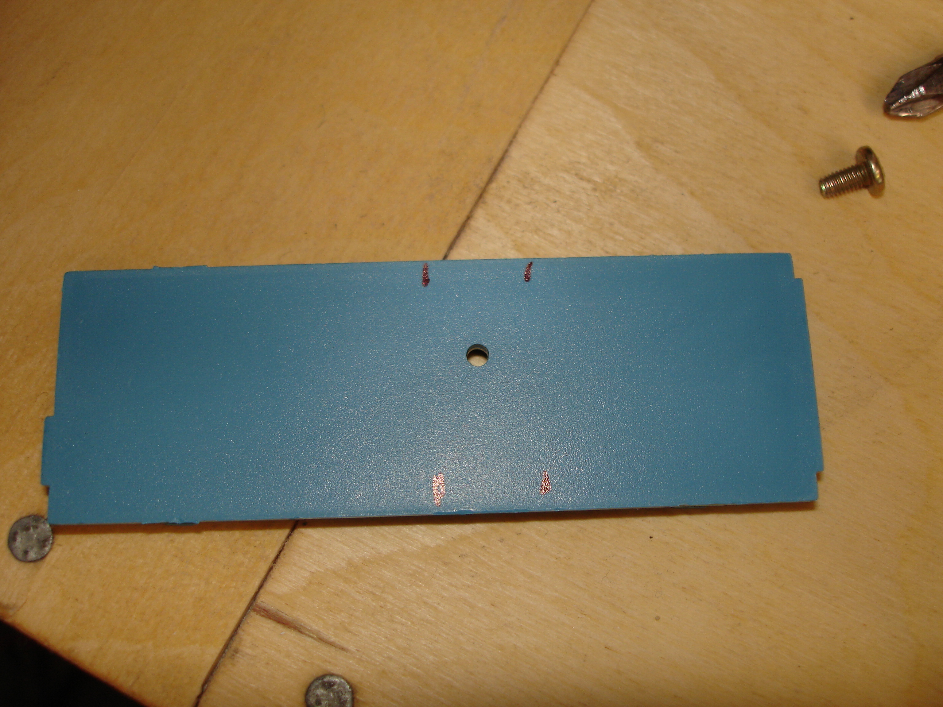
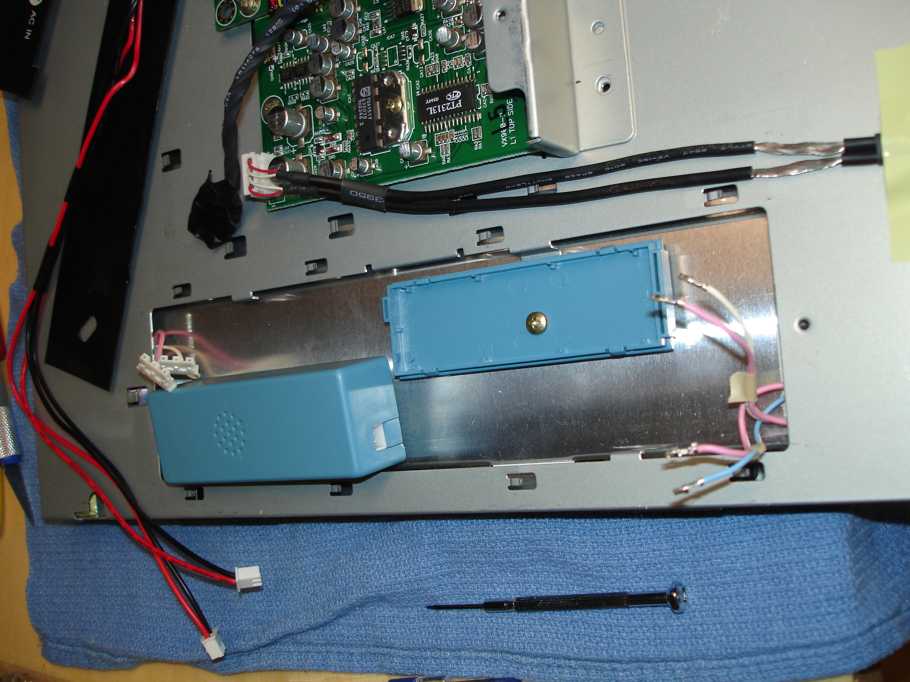

Image Notes
1. Good place to put the screw in the large green break under the transformer, just watch out for high voltage!
2. Make sure you mark out a go-no go region before drilling
3. Screwed to existing mounting brackets well within reach of the original wires
4. Even though we're in a place where nothing could touch, put some electrical tape down just in case anything ever comes loose.
Step Five: Wire up the Back Lights
The final step is to safely wire up the backlight CCFL bulb wires. Of course my connectors wouldn't fit in the other connector body so there was no other way than to
solder the connections on.
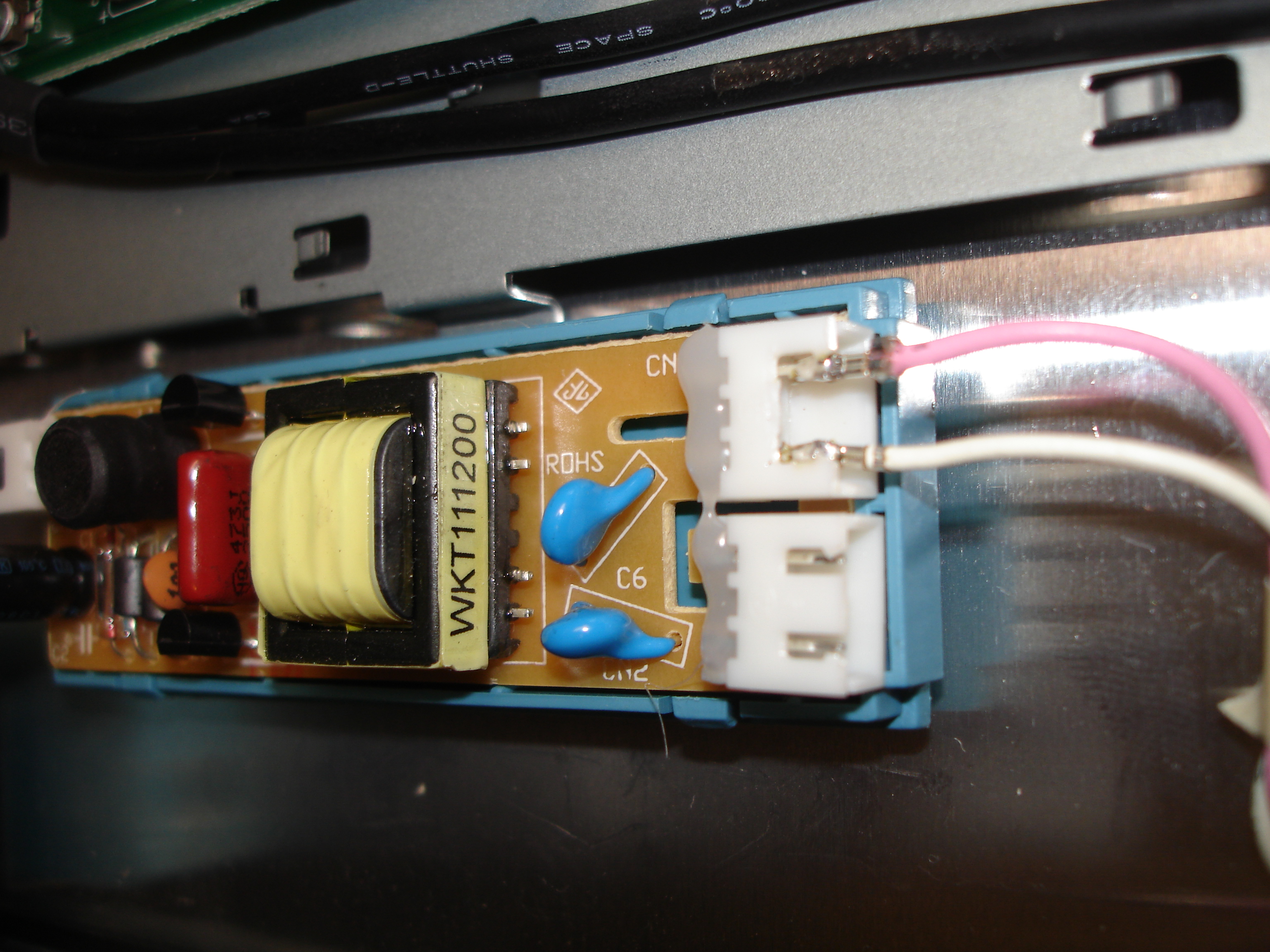
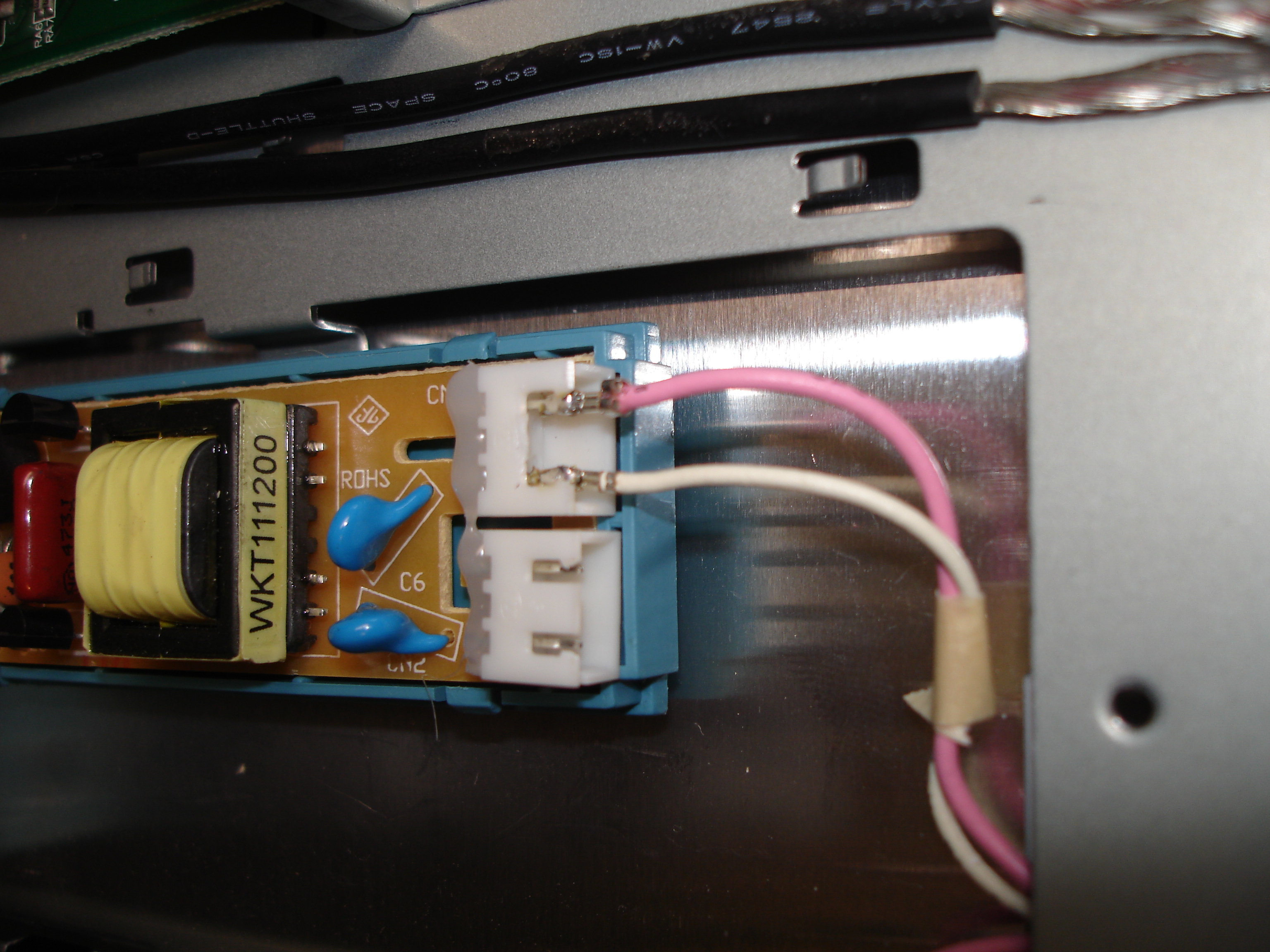
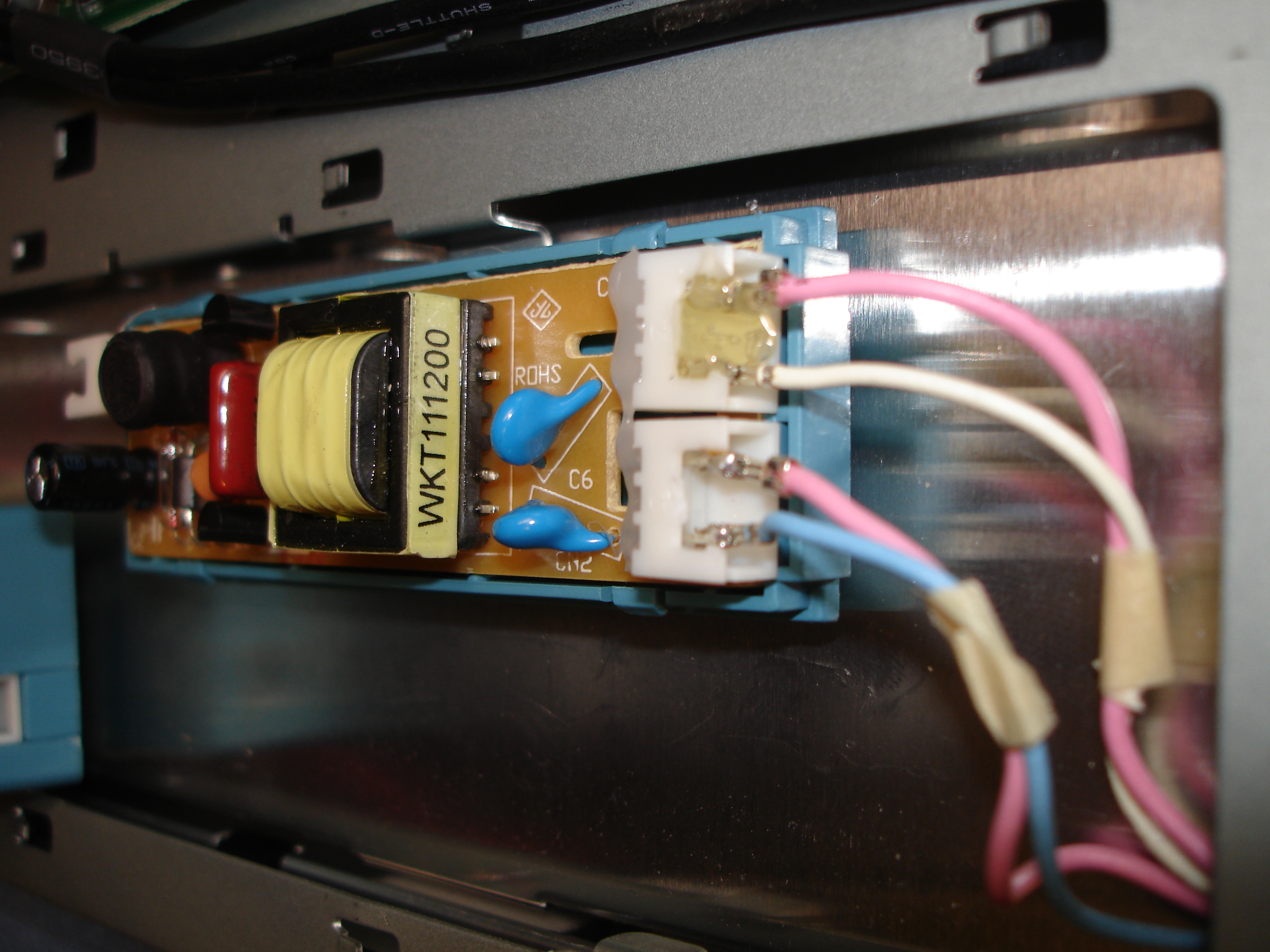
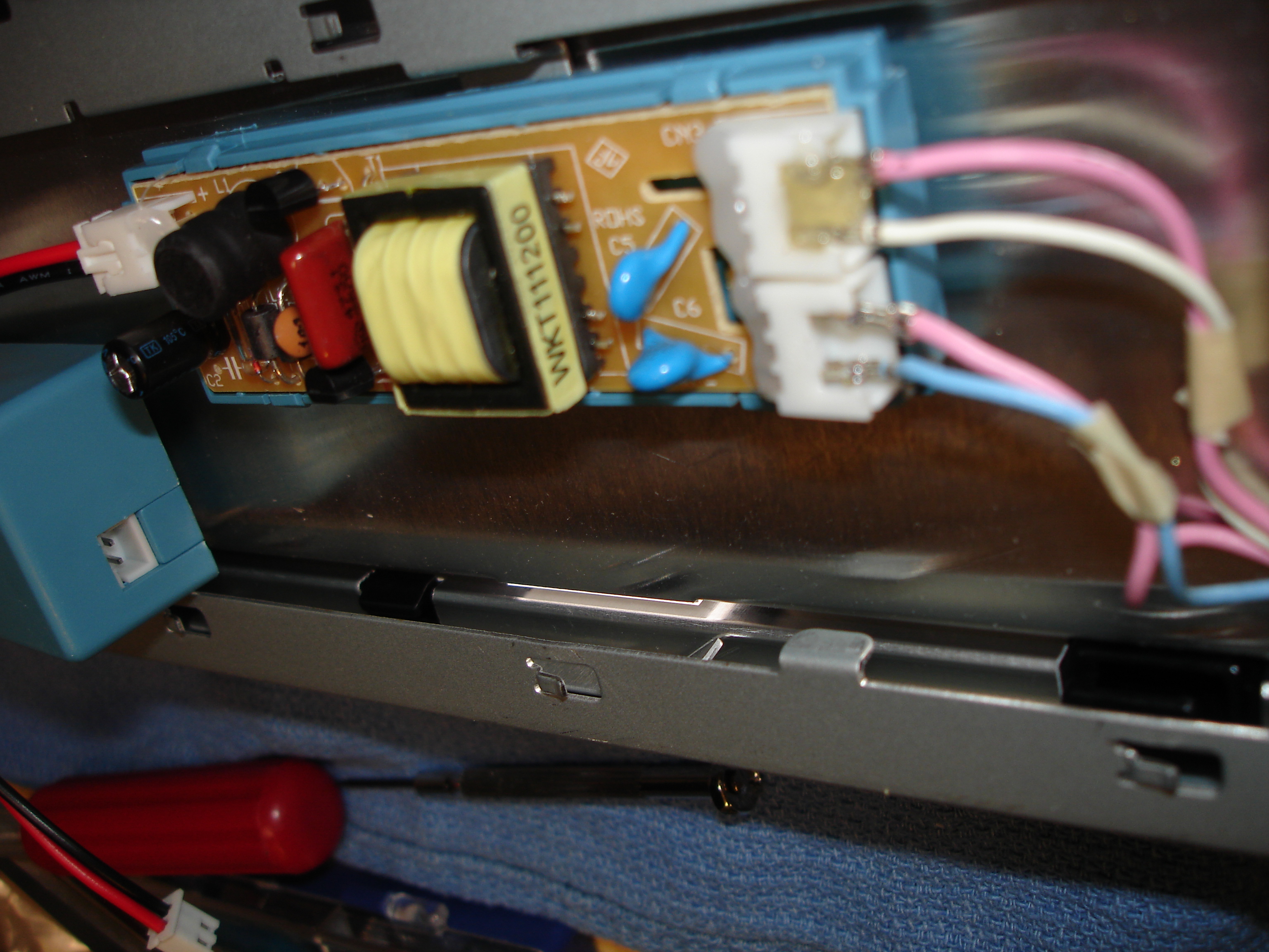
Image Notes
1. I cut the middle piece out of the connector and removed the connection from the plug body and then pushed the connections over the bare pin and soldered them in place
2. Then added solder
3. Then added hot glue to make sure they aren't going anyplace
4. And repeat for the other side.
1. I cut the middle piece out of the connector and removed the connection from the plug body and then pushed the connections over the bare pin and soldered them in place
2. Then added solder
3. Then added hot glue to make sure they aren't going anyplace
4. And repeat for the other side.
Step Six: Test it out and Reassemble
Once you've got both inverters mounted up it would be best to power it all up and see if it works. At this point I realized that I'd need a switch to control the backlights, so I'll show those pictures as well - remember that a better solution is to run a relay off of the original sleep/standby signal that runs to the inverter, I didn't have any relays handy so I didn't.
Enjoy!
Enjoy!
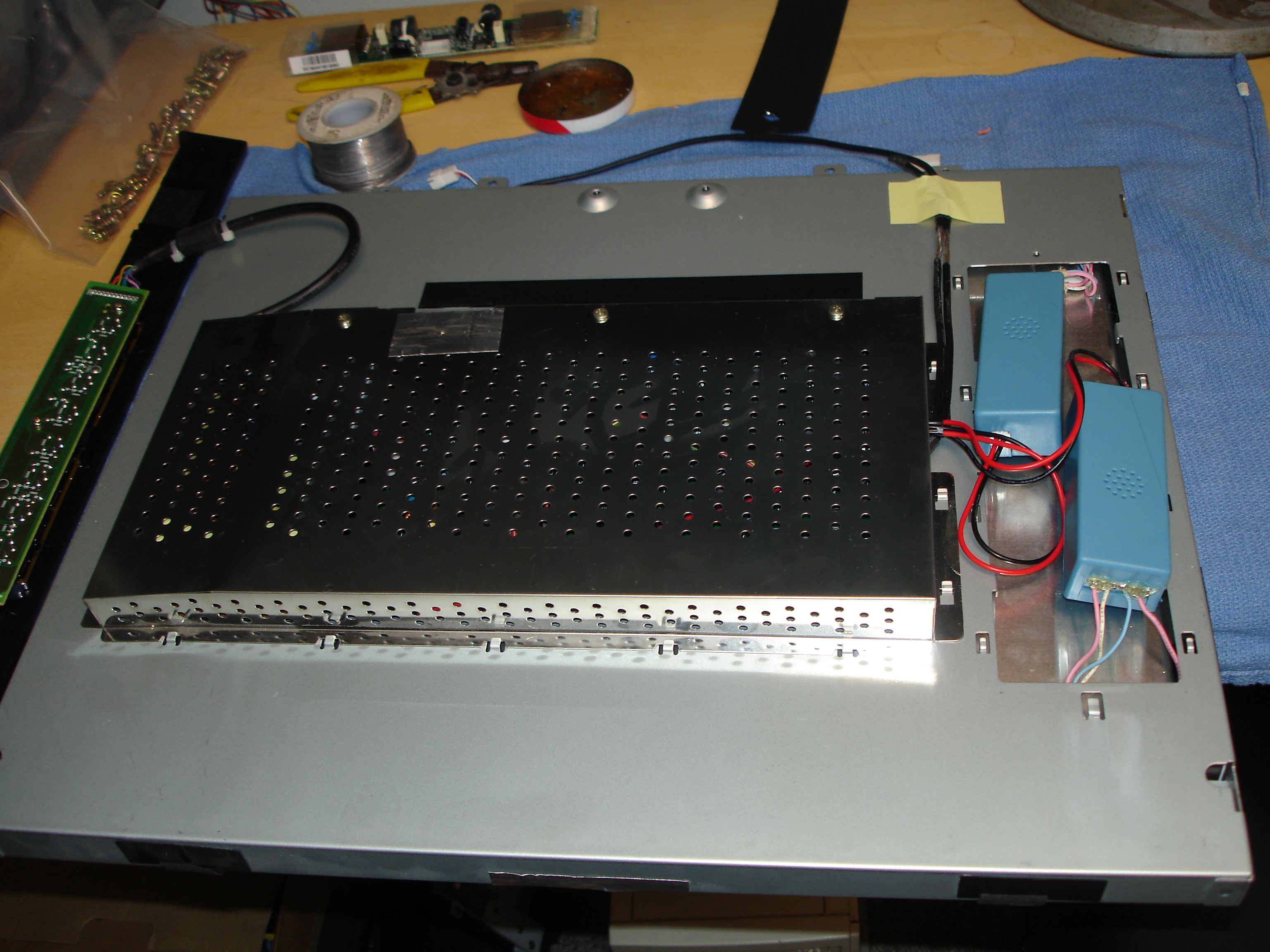

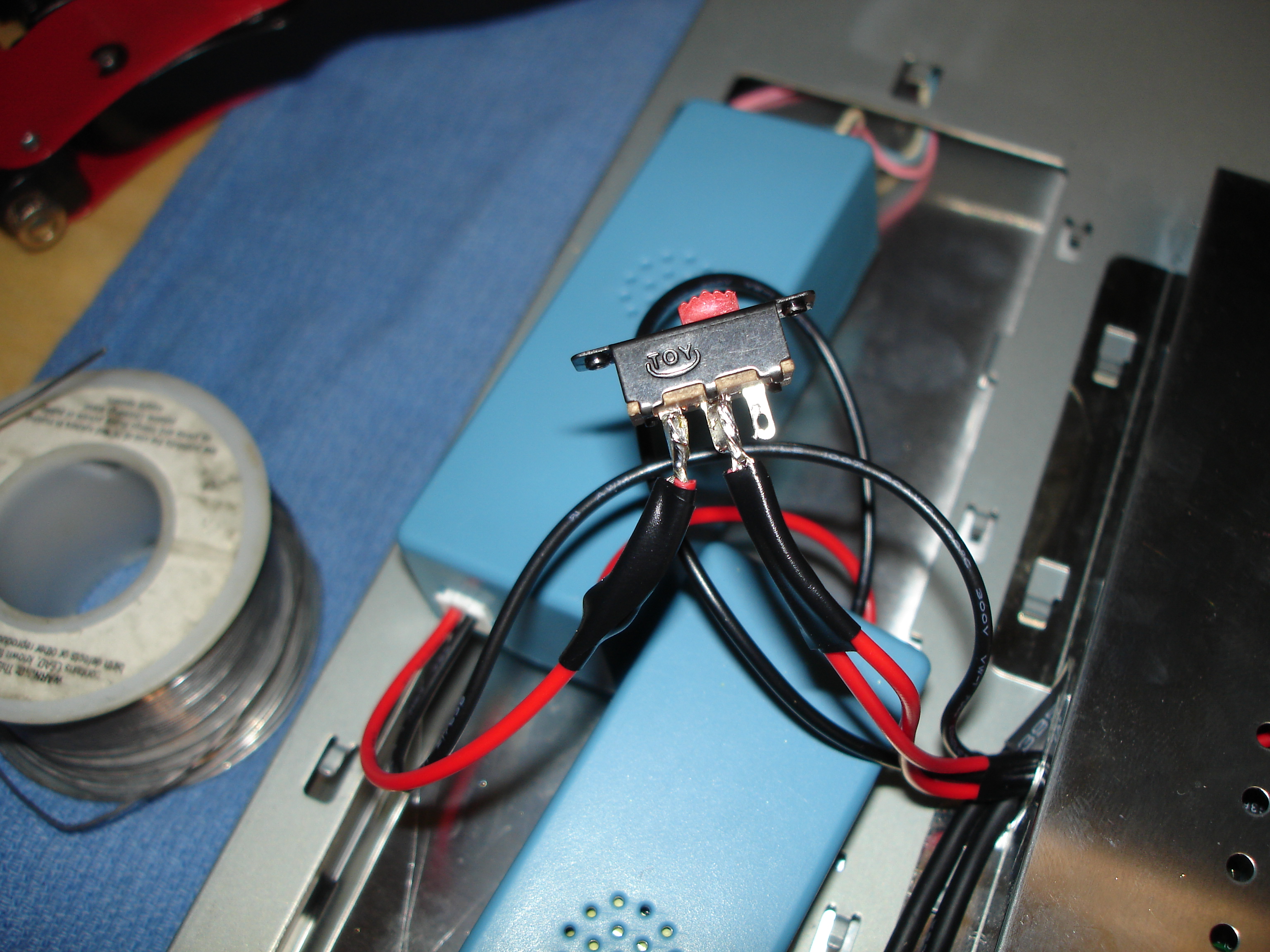
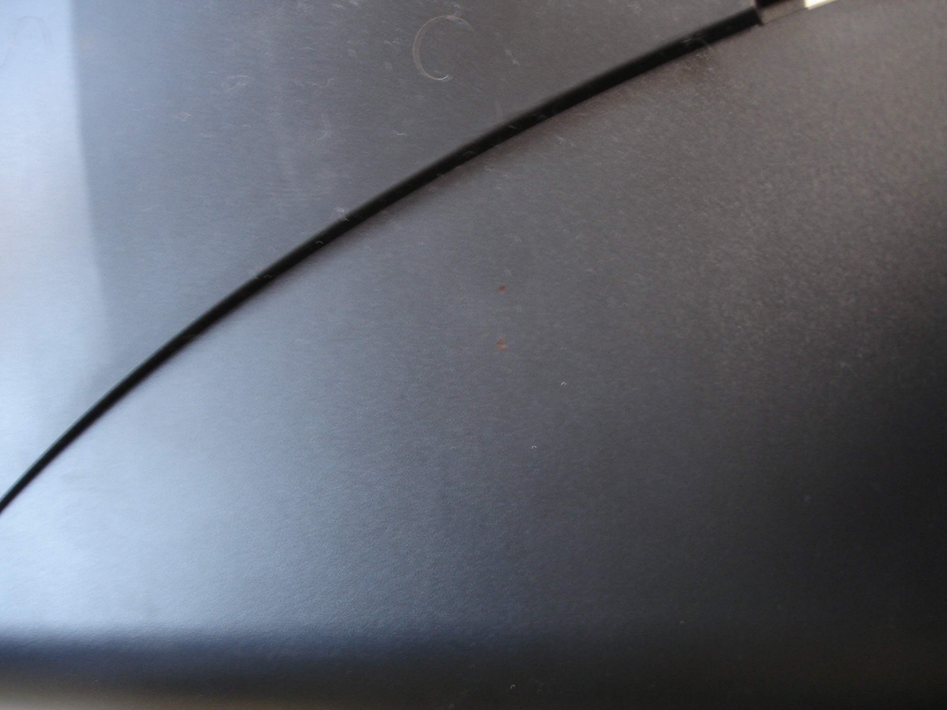
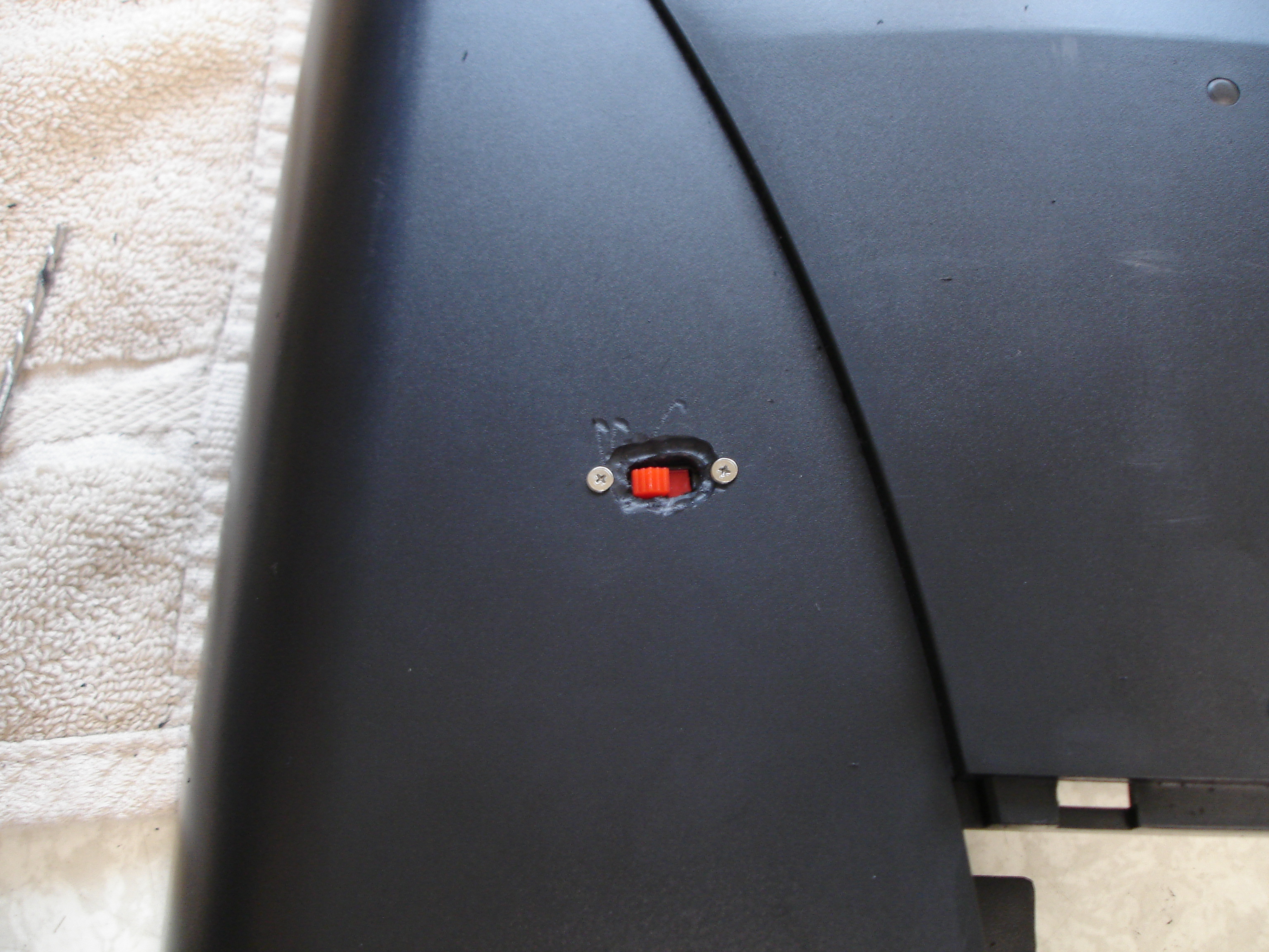
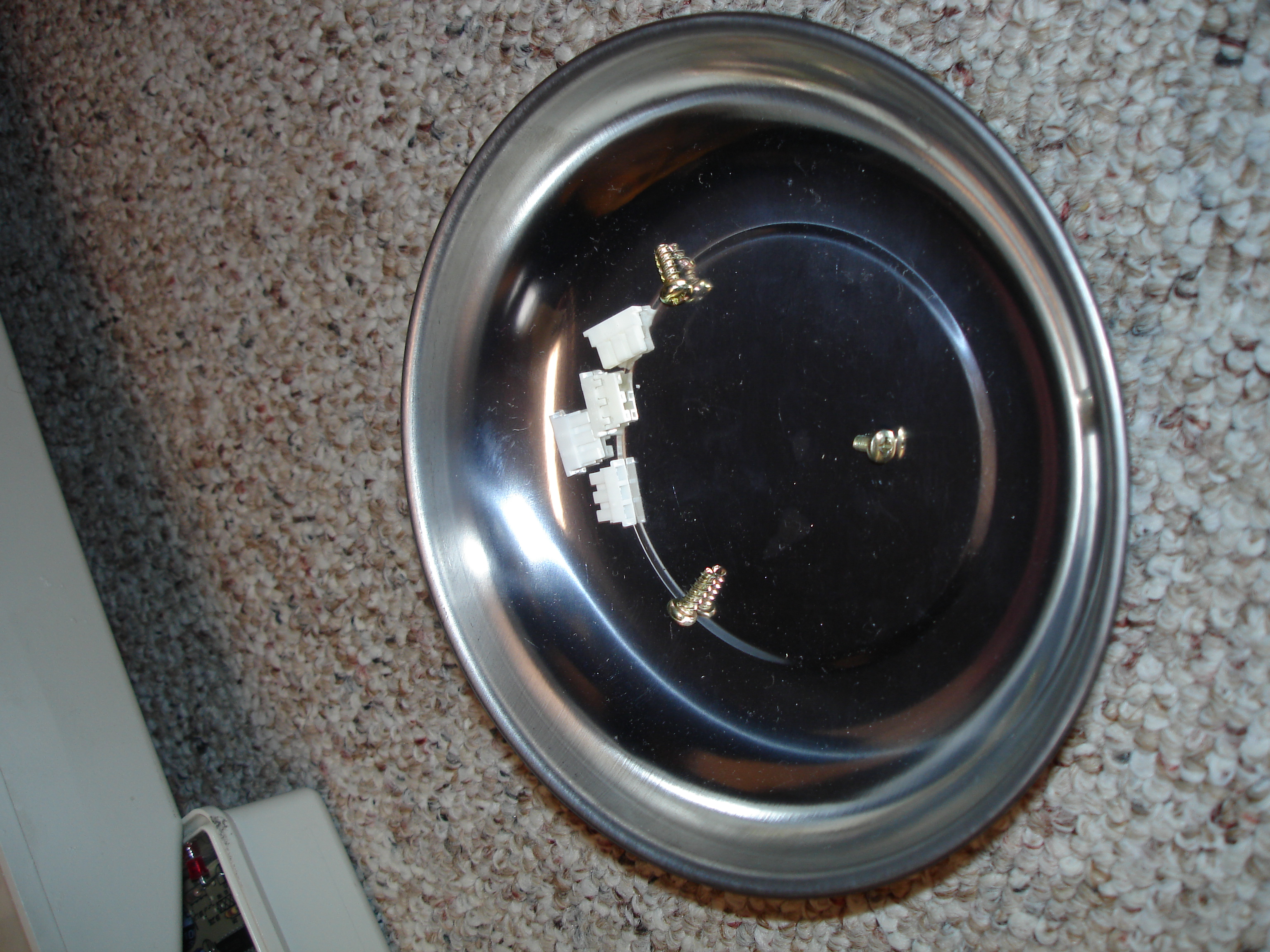
Image Notes
1. Get them both in place and replace covers
2. Power it up and check out your work!
3. Cut the positive 12V power to the inverters and wire it though the switch, a MUCH better solution is to run it through a relay off the original inverter power/standby signal
4. Mark out mounting position
5. Do a better job dremeling than me though ;)
6. Always end up with an extra screw, oh well, weight savings!